Tampilkan postingan dengan label Pengendali. Tampilkan semua postingan

Jumat, 19 Juli 2013

Skema rangkaian pengontrol suhu dengan LM35DZ


Sebelumnya kami telah memberikan postingan mengenai skema rangkaian penetas telur otomatis. Rangkaian ini cara kerjanya tidak jauh berbeda yakni untuk mengontrol suhu ruangan agar konstan pada suhu tertentu. Rangkaian ini outputnya menggunakan relay yang bisa diaplikasikan misalnya untuk mesin penetas telur otomatis, atau untuk menggerakan kipas angin di ruangan, atau untuk pengontrol suhu di mobil. Rangkaian ini memakai sensor suhu LM35DZ.  Ketika LM35DZ mendeteksi suhu lebih tinggi dari tingkat preset (ditetapkan oleh VR1), maka relai akan bekerja. Ketika suhu turun di bawah suhu preset, relay akan mati. Rangkaian dapat didukung oleh AC atau DC 12V pasokan daya atau baterai (100mA min.).

Skema rangkaian
Skema rangkaian pengontrol suhu LM35DZ
Layout PCB

Layout pcb pengontrol suhu LM35DZ

Daftar komponen:
IC1 : LM35DZ
IC2 : TL431
IC3 : LM358
LED1 – 3mm or 5mm LED
Q1 – General purpose PNP transistor ( A1015,…) with E-C-B pin-out)
D1, D2 — 1N4148
D3, D4 — 1N400x (x=2,,,,.7)
ZD1 — Zener diode, 13V, 400mW
Preset (trim pot) : 2.2K (Temperature set point)
R1 – 10K
R2 – 4.7M
R3 – 1.2K
R4 – 1K
R5 – 1K
R6 – 33Ω
C1 – 0.1 µF ceramic or mylar cap
C2 – 470 µF or 680 µF electrolytic cap. (16V min)
Relay – DC12V DPDT, Coil = 400 Ω or higher

Sumber: http://www.escol.com.my

Senin, 18 Maret 2013

Skema rangkaian mesin penetas telur otomatis

Skema rangkaian penetas telur otomatis ini cukup sederhana dan mudah untuk dibuat. Komponen utama dari rangkaian ini adalah thermistor. Thermistor adalah komponen atau sensor elektronika yang dipakai untuk mengukur suhu. Prinsip dasar dari termistor adalah perubahan nilai tahanan (atau hambatan atau werstan atau resistance) jika suhu atau temperatur yang mengenai termistor ini berubah. Dengan sensor ini tentunya kita bisa mengatur suhu ruangan sesuai dengan yang kita inginkan. Oleh karena itu skema rangkaian ini bisa dipakai untuk mesin penetas telur otomatis. Mesin penetas telur otomatis itu pada prinsipnya ketika suhu meningkat lebih dari seharusnya atau setelannya maka pemanas atau lampu akan padam atau kipas penyedot akan menyala. Dan ketika suhu ruangan melewati batas suhu terendah maka pemanas atau lampu akan menyala. Skema rangkaian yang saya berikan ini sangat tepat dengan prinsip atau cara kerja dari sebuah mesin penetas telur otomatis.

Skema rangkaian penetas telur otomatis
Transistor menggunakan jenis PNP misal  ZT2284 atau BC557 atau BD140

Ilustrasi penempatan alat:


Cara kerja rangkaian:

Suhu ruangan untuk mesin penetas telur biasanya 37.8° C atau 100° F. Ketika suhu ruangan diatas 38°C relay akan bekerja untuk menghidupkan kipas penyedot dan mematikan lampu. Ketika suhu ruangan turun dibawah 37° C maka relay mati dan lampupun menyala. Lamanya relay bekerja diatur oleh VR2 (Hysteresis= perbandingan suhu tertinggi dengan terendah). Perbedaan suhu hanya berkisar 0.5°-1°. . VR1 mengatur tinggi rendahnya suhu yang ingin dicapai. VR3 untuk menghaluskan pengaturan suhu yang ingin dicapai.

Catatan:
Relay yang digunakan menggunakan relay yang 2 Pin, Pin pertama untuk kipas, dan pin satunya lagi bisa digunakan untuk menyalakan dan mematikan lampu. Ketika relay mendapat tegangan atau lagi bekerja maka lampu mati demikian pula sebaliknya ketika relay tidak mendapat tegangan maka lampu menyala. Jadi tidak usah membuat rangkaian yang kedua.

Sumber:  http://www.craig.copperleife.com

Jumat, 15 Maret 2013

Pengendali motor servo dengan generator pulsa

Skema Rangkaian Motor Servo Controller atau Pengendali Motor Servo ini adalah desain dasar yang sederhana dari pengendali motor servo dengan generator pulsa. Ia menggunakan IC CMOS 7555 dalam modus astabil untuk menghasilkan pulsa untuk menggerakkan motor servo. Rangkaian dapat dimodifikasi sesuai untuk mendapatkan pulsa cukup panjang.

Servo adalah perangkat kecil yang memiliki poros output. Poros ini dapat diposisikan ke posisi sudut tertentu dengan mengirimkan servo sinyal kode. Selama sinyal kode ada pada baris masukan, servo akan mempertahankan posisi sudut dari poros. Posisi sudut poros ditentukan oleh durasi pulsa yang diterapkan pada kawat kontrol. Ini disebut Pulse Modulation Coded.

Servo biasanya membutuhkan pulsa setiap 20 milidetik (.02 detik). Panjang pulsa akan menentukan seberapa jauh motor berubah. Umumnya, 1,5 milidetik pulsa akan membuat pergantian motor ke posisi 90 derajat. Ini disebut Posisi Netral. Jika denyut nadi lebih pendek dari 1,5 ms, motor akan mengubah poros untuk dekat dengan 0 derajat. Jika denyut nadi lebih panjang dari 1.5ms, poros berubah mendekati 180 derajat.


Cara Kerja:
 Rangkaian ini dirancang untuk memberikan sinyal kontrol ke Servo.IC1 ini dirancang sebagai vibrator multi astabil yang dapat memberikan pulsa untuk pengoperasian Servo tersebut. The VR2 10KPot, R1 dan kapasitor C1 menentukan waktu Tinggi dan Rendah pulsa. Karena VR2 adalah variabel, waktu Tinggi bervariasi dari 2,07 menjadi 1,03 mS mS. Waktu yang rendah akan menjadi 40,5 mS. Dengan menyesuaikan VR1, mudah untuk mendapatkan timing.VR3 yang tepat menyesuaikan tegangan 1,6 volt kontrol ke pin kontrol 5 dari IC1.


Sebuah kontrol tegangan juga bisa dipasok dari luar. Kemudian VR3 harus dihilangkan. Kontrol tegangan dapat disediakan dari power supply variabel yang memberikan output 0-10 volt. Kontrol tegangan akan mengontrol posisi motor servo yang terhubung ke output. Ketika perubahan kontrol tegangan, servo akan bergerak ke posisi baru yang sesuai dengan nilai tegangan kontrol baru. 0 volt menyebabkan servo untuk tetap di satu ujung dan 10 volt ke ujung yang lain. Jika volt kontrol 5 volt servo tetap di posisi tengah. 

Sumber:  http://electroschematics.com

Rabu, 30 Mei 2012

Kontrol Mute Volume Sentuh

Rangkaian kontrol mute volume ini sangat sederhana dengan hanya mengandalkan satu buah ic pintar NE555. Rangakain ini bisa digunakan untuk rangkaian Audio Amplifier anda atau rangkaian saklar lainnya sebagai On-Off suatu rangkaian....
Here is another simple circuit to mute the volume of Audio devices through simple touch. It exploits the action of the flip-flops in the timer IC 555 to reduce the volume of the Audio amplifier. IC NE555 is designed in the toggle mode. Its lower and upper comparator inputs are connected to the touch plates which can be membrane switches or two pieces of conducting plates. The inputs of comparators are stabilized through R1 and R2 to avoid floating.

Touch controlled Mute switch circuit
Circuit Project: Touch controlled Mute Switch
When the touch plate connected to pin 2 is touched momentarily, output of IC1 goes high and T1 conducts. The centre tap of the volume control is connected to the collector of T1. So when T1 conducts current going to the amplifier drains through T1. This reduces the volume.IC1 remains latched in this position with LED on. When the touch plate connected to pin 6 is touched momentarily, output of IC1 goes low and T1 turns off. This restores the volume.

Source:  www.extremecircuits.net

Minggu, 22 April 2012

Rangkaian Pengendali Motor DC model Darlington

Kumpulan Skema Elektronika, A normal variable resistor cannot directly control the speed of a motor since motors draw large amounts of current which would burn out the potentiometer. Instead, the small amount of current that the potentiometer can pass can be amplified into order to run the motor. This amplification can be achieved using Darlington Pair of transistors.

Rangkaian Pengendali Motor DC
Pin-out BFY61 & TIP31C Transistor

The circuit above shows a linear potentiometer connected Between Vs and 0V Such That the voltage at its wiper terminal will of always be somewhere at or Between these two voltages. The small amount of current flowing out of the potentiometer's wiper is amplified by two transistors, connected together in a configuration known as a 'Darlington pair'. The current from the potentiometer is amplified by the first transistor, and then again by the second transistor, greatly Increasing the amount of current That cans be controlled by the potentiometer.

There are, however, a couple of disadvantages of this simple circuit. Firstly, about 0.7V is lost in EACH of the transistor, so the maximum voltage cans That ever be applied to the motor is Vs - 1.4V. Secondly, the transistors are not absolutely linear so the change in motor speed for a given rotation of the potentiometer will from some more subtle in the middle of its range. Because a motor is an inductive load, it will from Produce a 'back-emf' Could the which damage to the second transistor. The 1N4148 signal diode prevents this damage by shorting out the back-emf.

The power supply for this circuit should preferably be un-smoothed (i.e. directly from the power supply rectifier). This helps prevent the motor 'sticking' at low speeds. With the TIP31C transistor given, the maximum power supply voltage may be 60V and the maximum motor current consumption may be 3A.

Source: www.eleinmec.com

Sabtu, 31 Maret 2012

Rangkaian Kontrol Kecepatan Wiper Mobil

For some car wiper speed sometimes just made some speed so that less appropriate when we want a different speed, but for those of you who want a digital wiper speed controller you can also use this circuit to replace your old system.

rangkaian kontrol kecepatan wiper mobilSkema rangkaian kontrol kecepatan wiper mobil

This circuit comprises 2 timer NE555 ICs, one CD4017 decade counter, one TIP32 driver transistor, a 2N3055/ TIP3055 power transistor and A Few other discrete components. Timer IC1 is configured as a mono-stable multivibrator produces a pulse Pls Which one presses switch S1 momentarily. This pulse acts as a clock pulse for the decade counter (IC2) Which advances by one count on Each successive clock pulse or the push of switch S1. Ten presets (VR1 through VR10), for Different sets of values by trial and error, Are Used At The ten outputs of IC2. But since only one output of IC2 is high at a time, only one preset (selected at the output) effectively comes in series with resistors R4 and R5 timing connected in the circuit of timer IC3 Which functions in astable mode. As presets VR1 through VR10 are set for Different values, Different time periods (or frequencies) for astable multivibrator IC3 Can be selected. The output of IC3 is applied to the pnp driver transistor TIP32 for driving the final power transistor 2N3055 Which in turn drives the wiper motor at the selected sweep speed. The power supply for the wiper motor as well as the circuit is tapped from the vehicle s battery Itself. The duration of the monostable multivibrator IC1 is set for a period of nearly one second.

Source : www.electronic-circuits-diagrams.com

Senin, 26 Maret 2012

Ultrasonic Remote Control (Rangkaian Remot kontrol Ultrasonic)

This is a remote control circuit employing ultrasonic signals. The ultrasonic transmitter circuit is build around IC1(NE 555). IC1 is an astable multi vibrator operating at 40KHz.The output of IC1 is amplifier the complementary pair of transistors ( Q1 & Q2) and transmitted by the ultrasonic transmitter K1. The switch S1 is used activate the transmitter.

remote ultrasonicSkema rangkaian remote Control ultrasonic

Note:
  • switch S1 can be a push button switch.
  • The preset R16 can be used to adjust the sensitivity of the receiver.
  • The frequency of the ultrasonic signal can be varied by adjusting the preset R17.Adjust it for optimum performance.


The ultrasonic receiver uses an sensor transducer (K2) to sense the ultrasonic signals. When an ultrasonic signal is falling on the sensor, it produces a proportional voltage signal at its output. This weak signal is amplified by the two stage amplifier circuit comprising of transistors Q3 and Q4.The output of the amplifier is rectified by the diodes D3 & D4.The rectified signal is given to the inverting input of the opamp which is wired as a comparator. When ever there is an ultrasonic signal falling on the receiver, the output of the comparator activates the transistors Q5 & Q6 to drive the relay. In this way the load connected via the relay can be switched. The diode D5 is used as a free wheeling diode.


Features IC CA3140


  • Very High Input Impedance (ZIN) -1.5TΩ (Typ)
  • Very Low Input Current (Il) -10pA (Typ) at ±15V
  • Wide Common Mode Input Voltage Range (VlCR) - Can be wung 0.5V Below Negative Supply Voltage Rail
  • Output Swing Complements Input Common Mode
  • Directly Replaces Industry Type 741 in Most Applications
  • Pb-Free Plus Anneal Available (RoHS Compliant)


Pin Connection Ic NE 555


  • Ground, is the input pin of the source of the negative DC voltage
  • Trigger, negative input from the lower comparators (comparator B) that maintain oscillation capacitor voltage in the lowest 1 / 3 Vcc and set RS flip-flop
  • Output, the output pin of the IC 555.
  • Reset, the pin that serves to reset the latch inside the IC to be influential to reset the IC work. This pin is connected to a PNP-type transistor gate, so the transistor will be active if given a logic low. Normally this pin is connected directly to Vcc to prevent reset
  • Control voltage, this pin serves to regulate the stability of the reference voltage negative input (comparator A). This pin can be left hanging, but to ensure the stability of the reference comparator A, usually associated with a capacitor of about 10nF to berorde pin groun
  • Threshold, this pin is connected to the positive input (comparator A) which will reset the RS flip-flop when the voltage on the capacitor from exceeding 2 / 3 Vc
  • Discharge, this pin is connected to an open collector transistor Q1 is connected to ground emitternya. Switching transistor serves to clamp the corresponding node to ground on the timing of certain
  • Vcc, pin it to receive a DC voltage supply. Usually will work optimally if given a 5-15V. the current supply can be seen in the datasheet, which is about 10-15mA.

Minggu, 25 Maret 2012

Temperatur Controlled Fan (Pengontrol Suhu Kipas Angin)


This circuit controls very accurately a fan of any size. Just adjust the associated resistors for a different type like the R6 resistor of 100 ohm, 2 watt type and you're all set. The above circuit diagram is for a small 12 volt fan, the size and type determined by the user.


Parts List:
R1 = 560 ohm Q1 = 2N2907 (NTE159M) low noise
R2,R9 = 100K Q2 = MJE521 (NTE184)
R3,R8 = 10K IC1 = 741, op-amp
R4,R7 = 1K Led1 = LED, red
R5 = 470 ohm D1,D2,D3 = 1N4148, signal diode
R6 = 100 ohm, 2watt, wire-wound D4 = 1N4004, general purpose diode
P1 = 100K, trimmer pot

C1 = 2.2uF, 25V, electrolytic
C2 = 47uF, 25V, electrolytic

This circuit controls very accurately a fan of any size. Just adjust the associated resistors for a different type like the R6 resistor of 100 ohm, 2 watt type and you're all set. The above circuit diagram is for a small 12 volt fan, the size and type determined by the user.

Temperature is sampled via the 1N4148 diodes and presented at pins 2 and 3 of the differential type 741 op-amp. R7 (10K) is used to create a voltage difference between the inverted and non-inverted input pins 2 and 3 of the 741. All signals presented at pin 2 will be inverted on the output pin 6. Obviously then, the input pins are very important. When pin 2 goes more positive than pin 3, the output pin 6 of the 741 goes high and forward biasing the base of transistor Q1, which switches on transistor Q2 and the Led and puts 12V on the output pins for the fan. R9 functions as a feedback for the 741. Only DC type fans can be used with this schematic diagram without further modifications.

The temperature sensor is made up of three easily available 1N4148 signal diodes mounted in parallel. Mount them in a thin aluminum, or plastic tube (depending on your application) and silicon the end of the tube to make this temperature sensor water-proof. As an additional note, I have seen this type of temperature sensor, with the diodes either in parallel or series and either 1 or more diodes, in all sorts of laboratory equipment like hot water baths and others. The water bath temperature setting ranged from room temperature to about 100° Celsius. Keep in mind that using the 1N4148 diode as a temperature sensor is very accurate when used within the specifications of the 1N4148.

Jumat, 23 Maret 2012

Rangkaian Lampu mati nyala Otomatis

Rangkaian Lampu Halaman Belakang. Sebagai bagian dari bangun rumah, halaman belakang biasanya ada. Beragam fungsi serta peran yang dimainkannya. Halaman belakang, menjelma menjadi taman-taman indah nan artistik, penuh sentuhan nilai seni pada rumah yang mewah. Tak jarang, kolam renang dengan air kebiruan menjadi pelengkapnya. Di lain pihak, halaman belakang adalah tempat menimbun perkakas yang tidak penting dari suatu
rumah sederhana yang kelebihan perabot.
Tempat bercengkerama keluarga, menyatukan pendapat, berbagi cerita dan cinta. Wahana menikmati secangkir teh, susu atau kopi panas di pagi hari sambil membaca koran. Di sore hari, halaman belakang bisa menjadi tempat pelepas lelah dan penat setelah seharian bekerja. Kursi malas dengan busa empuk, meja-meja bundar bercita rasa seni, tumpukan koran dan buku, beberapa toples cemilan akan lengkap dinikmati di halaman belakang.
Pada kesempatan kali ini saya akan mengetengahkan dan memperkenalkan sebuah rangkaian, yakni Rangkaian Lampu Halaman Belakang.

Rangkaian ini akan bekerja/berfungsi dari pukul 10 malam sampai pagi. Hal ini membantu untuk memberikan cahaya di halaman belakang guna menghindari binatang malam dan bahkan mencegah upaya pencurian. Rangkaian ini sepenuhnya otomatis dan menggunakan LDR sebagai saklar peka cahaya.
Rangkaian memiliki power supply tanpa trafo  dan rangkaian saklar berbasis waktu. Kapasitor C1, dioda D1 dan kapasitor C2 melalui D4 membentuk bagian power supply. C1 adalah X rated kapasitor AC. Tinggi volt AC berkurang ke tingkat yang lebih aman dengan C1 melalui properti rectance. Dioda D1 melalui D4 membentuk penyearah gelombang penuh untuk mengubah AC ke DC dan kapasitor C2 menghilangkan riak dari DC. Resistor R1 adalah resistor pemeras untuk menghapus saat disimpan dari C1 ketika rangkaian dimatikan. Resistor R2 mengurangi lonjakan arus ke rangkaian.
LDR digunakan di Rangkaian Lampu Halaman Belakang untuk memicu IC1 di saat matahari tenggelam (senja). Hambatan dari LDR sangat tinggi sekitar 10 megaohm  pada waktu gelap dan berkurang sampai 100 ohm di waktu sinar matahari cerah. IC CD 4060 adalah pilihan yang baik untuk aplikasi delay waktu yang lama. IC1 adalah kontra biner dengan sumber osilator internal dan 10 output. Selama siang hari, resistensi dari LDR akan rendah sehingga reset pin 12 dari IC1 tetap tinggi yang menghambat kerja dari IC1. Saat matahari terbenam, resistansi LDR meningkat dan 12 pin reset IC akan membumi dan mulai berosilasi dengan komponen, C3, R4 dan R5.  LED merah bersinar mengindikasikan aktivasi dari IC1. Dengan nilai yang diberikan dari C3, R4 dan R5, pin 1 menjadi tinggi setelah 4 jam, yaitu sekitar 10 malam.

Sumber:  http://www.electroschematics.com

Light Control Switch


Rabu, 21 Maret 2012

Rangkaian Fan Control Suhu Otomatis

 Control suhu otomatis
Skema rangkaian fan control suhu otomatis
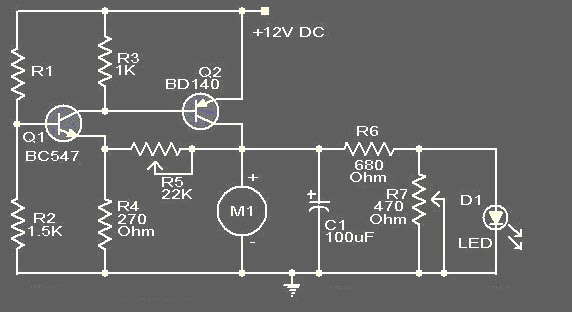
This circuit of automatic Control suhu is based on two transistors that can be used to control the speed of a 12 V DC fan depending on the temperature (suhu). A thermistor (R1) is used to sense the temperature. When the temperature increases the base current of Q1 (BC 547) increases which in turn decreases the collector voltage of the same transistor. Since the collector of Q1 is coupled to the base of Q2 (BD 140), the decrease in collector voltage of Q1 forward biases the Q2 more and so do the speed of the motor. Also, the brightness of the LED will be proportional to the speed of the motor.
Note:
  • R1 can be a 15K @ 20°C ,N.T.C thermistor.
  • M1: DC Fan 12V,700mA fan motor.
  • Capacitor C1 must be rated 25V.
  • The circuit can be powered from a 12V PP3 battery or 12V DC power supply.

About thermistor

The standard leaded thermistors are calibrated and tested at 20 °C to a tolerance of ± 5 % or ± 10 %; however, tighter tolerance, point matched thermistors are readily available as are special point match temperatures to fit your application. Since these thermistors have only one controlled point of reference (the point match temperature), the resistance at other
temperatures is given by the “Resistance vs. Temperature Conversion Tables” for the appropriate material curve. The resistance value at any temperature is the ratio factor times the resistance at 25 °C. The resistance vs. temperature conversion tables can
be found at: www.vishay.com/doc?33004 and www.vishay.com/doc?33011.

Rangkaian Control Lampu Jalan Dengan LDR

This circuit is of a street light that automatically switches ON when the night falls and turns off when the sun rises. In fact you can this circuit for implementing any type of automatic night light. This circuit can be used to control lights or other electrical equipment with large power to hundreds of watts
The circuit used an LDR to sense the light . When there is light the resistance of LDR will be low. So the voltage drop across POT R2 will be high. This keeps the transistor Q1 ON. The collector of Q1(BC107) is coupled to base of Q2(SL100). So Q2 will be OFF and so do the relay. The bulb will remain OFF.
When night falls the resistance of LDR increases to make the voltage across the POT R2 to decrease below 0.6V. This makes transistor Q1 OFF which in turn turs ON Q2.The relay will be energized and the bulb will glow.
 Control Lampu Jalan Dengan LDRSkema rangkaian control lampu jalan dengan LDR

* POT R2 can be used to adjust the sensitivity of the circuit.
* You can use bulb of any wattage ,provided that relay should have the sufficient rating.
* The circuit can be powered from a regulated 9V DC power supply.
* Click Here! to get the power supply circuit for this project.
* The relay K1 can be a 9V SPDT relay.

A bout LDR ( Light Dependent Resistor )

Working principle of LDR is the LDR resistance will change with changes in light intensity about it. In the dark resistance of LDR about 10MΩ and in light of 1KΩ or less. LDR is made from semiconductor materials such as cadmium sulfide. With this material the energy of the light that falls cause more load to the electric current is released or increased. This means that the material resistance has decreased.
LDR ( Light Dependent Resistor )
LDR ( Light Dependent Resistor ) pic
LDR is used to convert light energy into electrical energy. Automatic light switches and burglar alarms are a few examples of tools that use the LDR. However, because the response to light is slow, LDR is not used in situations where the intensity of light changed drastically.