Tampilkan postingan dengan label Rangkaian Termometer. Tampilkan semua postingan

Rabu, 21 Maret 2012

Rangkaian Termometer Digital

IC LM35
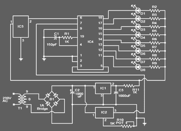
Skema rangkaian termometer digital
This circuit uses IC LM 35 to sense the temperature. output of LM 35 is given to the IC ADC 0804 (IC4) which converts the analog output of the LM 35 to digital output. The ADC 0804 is a 8 bit ADC .Eight LED’s are connected to the output of ADC to show the output logic.
If needed the LED’s can be avoided and the output can be connected to any suitable external circuit like temperature controller etc.A 5V fixed voltage regulator based on 7805 (IC1) powers the circuit.Another variable voltage regulator based on LM317(IC2) is used to provide the reference voltage to the ADC 0804.

Notes:
  • POT R10 can be used to adjust the scale factor of the ADC. The reference voltage at pin 7 of ADC0804 should be 2.5 V for full scale.
  • IC1: 7805, IC2: LM317, IC3: LM35, IC4 ADC0804
  • D1 TO D8: DIODE LED, R2 TO R8: 1K 1/2 WATT RESISTOR

Spesifikasi IC LM35

The LM35 series are precision integrated-circuit temperature sensors, whose output voltage is linearly proportional to the Celsius (Centigrade) temperature. The LM35 thus has an advantage over linear temperature sensors calibrated in ° Kelvin, as the user is not required to subtract a large constant voltage from its output to obtain convenient Centigrade scaling. The LM35 does not require any external calibration or trimming to provide typical accuracies of ±¼°C at room temperature and ±¾°C over a full -55 to +150°C temperature range. Low cost is assured by trimming and calibration at the wafer level. The LM35's low output impedance, linear output, and precise inherent calibration make interfacing to readout or control circuitry especially easy. It can be used with single power supplies, or with plus and minus supplies. As it draws only 60 µA from its supply, it has very low self-heating, less than 0.1°C in still air. The LM35 is rated to operate over a -55° to +150°C temperature range, while the LM35C is rated for a -40° to +110°C range (-10° with improved accuracy). The LM35 series is available packaged in hermetic TO-46 transistor packages, while the LM35C, LM35CA, and LM35D are also available in the plastic TO-92 transistor package. The LM35D is also available in an 8-lead surface mount small outline package and a plastic TO-220 package.


termometer digital

Feature IC LM35

•Calibrated directly in ° Celsius (Centigrade)
•Linear + 10.0 mV/°C scale factor
•0.5°C accuracy guaranteeable (at +25°C)
•Rated for full -55° to +150°C range
•Suitable for remote applications
•Low cost due to wafer-level trimming
•Operates from 4 to 30 volts
•Less than 60 µA current drain
•Low self-heating, 0.08°C in still air
•Nonlinearity only ±¼°C typical
•Low impedance output, 0.1 Ohm for 1 mA load

Selasa, 13 Maret 2012

Rangkaian Termometer

Rangkaian Thermometer Berbasis Mikrokontroler AT89S52
Skema Rangkaian Thermometer Berbasis Mikrokontroler AT89S52
This is a circuit of a microcontroller AT89S52 Thermometer and 12-bit ADC LTC1298, programs written in the language c program with digital filtering and interface the LED display. The reading provides 0.1C sensitivity.

The hardware block and circuit diagram is shown in Fig below. The sensor is epoxy molded thermistor. The circuit for signal conditioning is a simple voltage divider. The ADC is 12-bit SPI interface LTC1298 analog-to-digital converter. The microcontroller is Atmel 89S52. The display has four digits 0.5 inches 7-segment LED. The segment driver provides 32-bit CMOS output.


Rangkaian Thermometer Berbasis Mikrokontroler AT89S52
Thermometer Block Diagram


The ADC is 12-bit (LTC1298 or MC3202) are two channels, CH0 and CH1. The input signal from thermistor for ADC channel 0 is simple voltage divider. Channel1 is available for other sensor. The sample shown in schematic is HIH-3160 Honeywell Relative Humidity Sensor. The ADC chip is interfaced with MCU, 89S52 with P1.1, P1.2 and P1.3. The display has 4-digit LED. The 4094 CMOS shift register drives the LED directly.


Software

The main function is time triggered by 10ms timer0 running. The ADC is updated on LED every 10 ticks.

while(1)
{
while(!cputick)
continue;
cputick=0;
print_ADC();
}

The function that reads 12-bit data from ADC is read_ADC(char n). The function has two loops. First loop is to send 4-bit command. And the second loop is 12-bit to shift the data from ADC.

sbit Data = P1^1;
sbit CLK = P1^2;
sbit CS = P1^3;


int read_ADC(char n)
{ int k;
char i,channel;
k=0;
CS=0;
if(n==0) channel=0x0d;
else channel=0x0f;

for(i=0;i<4;i++) clk =" 0;" data =" 1;" data =" 0;" clk =" 1;" data =" 1;" clk =" 0;" i="0;i<12;i++)" clk="1;" clk="0;" cs =" 1;">

To provide smooth reading, I added the 5-point moving average to the raw data. The function low_pass_filte1( ) is used to filter the high frequency noise. The reading is calibrated to degree Celsius with Platinum 100 standard thermometer. We found the equation y=0.0323x-15.122.

int low_pass_filter1(void)
{
x5=x4;
x4=x3;
x3=x2;
x2=x1;
x1=read_ADC(0);
return(x1+x2+x3+x4+x5)/5;
}

float read_temp1_filter(void)
{
return(0.0323*low_pass_filter1()-15.122);
}