Tampilkan postingan dengan label FM Transmitter. Tampilkan semua postingan

Senin, 09 Juli 2012

Rangkaian Power Amplifier Pemancar FM 4-20 Watt

Rangkaian Power Amplifier Pemancar FM ini sangat sederhana, namun kualitasnya cukup memuaskan.

A very simple fm power amplifier which can deliver 4W rf power with 12V power supply and BLY87A or KT920A and 20W with BLY89A or KT925B.
If you use BLY87A or KT920A the input power must be 0.5W and 4W if you use BLY89A or KT925B. This fm power amplifier is designed to work on 50 Ω antennas and a maximum power supply of 14V and in 88 108 MHz band.
Use only metallic trimmers, a good heatsink for the transistor and ceramic capacitors and keep the pins very short.
FM power amplifier circuit components:
C1 = C8 = 10-40pF + 22pF in parallel ||
C2 = 10-70pF + 120pF ||
C3 = 2.2nF
C4 = 33nF
C5 = 4 x 180pF
C6 = 1nF
C7 = 2.2nF
C9 = 10-70pF + 47pF ||
R1 = 380Ω
R2 = 47Ω
R3 = 5.6 Ω
L1 = 3 turns / 0.8mm / 6mm / legth = 8mm
L2 = 6turns / 0.5mm /over R2
L3 = 5 t / 0.6mm / 6mm
L4 = 4 t / 1.2mm / 8mm
T = 4W with BLY87A, KT920A
T = 20W with BLY89A, KT925B

FM amplifier circuit schematic

 Source: http://electroschematics.com

Jumat, 29 Juni 2012

Kit Pemancar FM Setereo IC BA1404

Jadilah "On Air" dengan stasiun radio sendiri! Pemancar FM Ini merupakan produk menarik yang akan menyiarkan sinyal stereo berkualitas tinggi dalam 88 - 100MHz FM band. Hal ini dapat dihubungkan ke semua jenis sumber audio stereo seperti komputer pribadi, CD player, walkman, televisi, tape deck atau sistem stereo untuk mengirimkan suara stereo dengan kejelasan yang sangat baik di seluruh, kantor Anda pekarangan rumah, atau tanah kamp.
Hal ini juga dapat digunakan dalam mobil untuk memutar CD melalui radio mobil Anda ketika melekat pada CD player pribadi. Aplikasi lain dapat mendengarkan stasiun radio satelit melalui radio FM. Selain itu, dapat dihubungkan ke komputer pribadi atau laptop untuk memungkinkan mendengarkan stasiun radio internet atau pra-rekaman musik digital (seperti file MP3).


Sirkuit yang mencakup snap baterai 9V dan stereo 3.5mm jack dipasang tepat di papan tulis untuk koneksi yang mudah ke sumber audio. Sebuah ON / OFF serta "On-Air" indikator LED juga dimasukkan di papan tulis.


Source : http://home.maine.rr.com/randylinscott/feb98.htm
   
Rangkaian ini didasarkan pada IC BA1404 penyiar stereo populer yang berisi semua sirkuit kompleks untuk menghasilkan sinyal FM stereo. Sebuah kristal KHz 38 menyediakan stabil sub-carrier untuk sinyal stereo. Rangkaian osilator cukup stabil untuk penerimaan handal bahkan di radio FM digital disetel. Penyesuaian input terpisah kanan dan kiri tingkat juga disertakan.

Untuk memperoleh Kit ini anda bisa membelinya di CAR'L ELECTRONICS 

Senin, 25 Juni 2012

Pemancar FM menggunakan Op-amp

Sebuah Transmitter FM daya rendah menggunakan sebuah op-amp sebagai preamp audio dan satu transistor sebagai penguat RF.


List Component:

R1 4K7        R4 150K     R7 3K9 (2K7)

R2 4K7 R5 220R R8 120R (82R)

R3 4K7 R6 4K7

All resistors except R8 are at least 0.25W rated. R8 is at least 0.5W rated
(the 0.6W metal film M-series from Maplin can be used for R1-R8).

C1 1n C4 22uF C7 10n C10 1n

C2 4u7 C5 1n C8 1n

C3 1n C6 10n C9 33pF

VC1 5-60pF IC1 LM358 Q1 ZTX108

Notes
L1 is 0.112uH (this tunes to the middle of the FM band, 98 MHz, with VC1 at its centre value of 33pF).

L1 is 5 turns of 22 swg enamelled copper wire close-wound on a 5mm (3/16") diameter former. Alternatively, you can have a fixed 33pF cap instead of VC1 and have L1 as an adjustable molded coil (eg UF64U from Maplin). VC1 will give you a tuning range of 85 - 125 MHz, and a possible choice is the Philips type polypropylene film trimmer (Maplin code WL72P).

Two sets of oscillator bias resistors are given, the ones in the brackets give about 20% more RF power.

Mike is our favourite Omnidirectional sub-mini electret (Maplin code FS43W). Ant is a (lambda / 4) whip monopole (eg 76 cms of 22 swg copper wire).

Q1 is configured as a Clapp oscillator. Frequency modulation results from the audio voltage changing the transistor's base-emitter capacitance.

Source:  http://www.zen22142.zen.co.uk

Rabu, 28 Maret 2012

2 Watt FM Transmitter

The circuit is basically a radio frequency (RF) oscillator that operates around 100 MHz. Audio picked up and amplified by the electret microphone is fed into the audio amplifier stage built around the first transistor. Output from the collector is fed into the base of the second transistor where it modulates the resonant frequency of the tank circuit (L1 coil and the trimcap) by varying the junction capacitance of the transistor. Junction capacitance is a function of the potential difference applied to the base of the transistor T2. The tank circuit is connected in a Hartley oscillator circuit.

Components List

R1=220K
R2=4.7K
R3,R4=10K
R5=100ohm
C1,C2=4.7uF Electrolytic
C3,C4=1nF
C5=2-15pF
C6=3.3pF
Q1=BC547C
Q2=BD135
P1=25K
MIC=Electret Condenser Type
P1 act as condenser microphone volume level. For FM, coil will be small. Use thin gauge enamel magnet wire. the diameter of coil will be a couple mm: use ink tube from pen to form, and try 8-12 turns. Small inductance coils make for much guess work.

Stereo FM Transmitter Based BH1417 Chips

This electronic circuit is a latest BH1417 FM Transmitter design from RHOM that includes a lot of features in one small package. It comes with pre-emphasis, limiter so that the music can be transmitted at the same audio level, stereo encoder for stereo transmission, low pass filter that blocks any audio signals above 15KHz to prevent any RF interference, PLL circuit that provides rock solid frequency transmission (no more frequency drift), FM oscillator and RF output buffer.

There are 14 possible transmission frequencies with 200KHz increments that users can select with a 4-DIP switch. Lower band frequencies start from 88.7 up to 89.9 MHz, and upper band frequencies start from 107.7 up to 108.9 MHz.


BH1417 can be supplied with 4 - 6 voltage and consumes only around 30mA, providing 20mW output RF power. BH1417 provides 40dB channel separation which is pretty good, although older BA1404 FM Transmitter chip provides slightly better 45dB channel separation.


BH1417 is only available in SOP22 IC case so this may be an inconvenience for some folks. On the other hand, because the chip is smaller than regular DIP-based ICs it is possible to fit the entire transmitter on a small PCB.

The bad news is that BH1417 requires 7.6MHz crystal oscillator, which is very hard to find. The good news is that you can use 7.68 MHz crystal instead, which is easier to find. In fact our BH1417 transmitter prototype (schematic shown above) uses 7.68 MHz crystal. This has absolutely no effect on stereo encoding process, we have tested it and stereo sound is crystal clear. The transmitted frequency on the other hand will be shifted up by exactly 1MHz (example: 88.1 MHz to 89.1 MHz) which is perfectly fine. The frequencies that are used in this project have been adjusted by 1MHz already so no additional conversion is necessary.

BH1417 chip may also be used a stand alone stereo encoder. The advantage of that is that you have full freedom of using a transmitter & amplifier of your choice. You will still have a pre-emphasis, limiter,stereo encoder and low pass filter in one small package because very few external components are required for these blocks. PIN 5 is MPX output that can be directly connected to an external FM transmitter through a 10uF cap.


Parts List:
1x BH1417 - Stereo PLL Transmitter IC (Case SOP22) (datasheet)
1x 7.68 MHz Crystal
1x MPSA13 - NPN Darlington Transistor
1x 2.5 Turns Variable Coil
1x MV2109 - Varicap Diode
1x 4-DIP Switch
ANT - 30 cm of copper wire

1x 22K Resistor
7x 10K Resistor
1x 5.1K Resistor
2x 3.3K Resistor
1x 100 Ohm Resistor 1x 100uF Capacitor
3x 10uF Capacitor
2x 1uF Capacitor

1x 47nF Capacitor
3x 2.2nF Capacitor
1x 1nF Capacitor
1x 330pF Capacitor
2x 150pF Capacitor
1x 33pF Capacitor
2x 27pF Capacitor
1x 22pF Capacitor
2x 10pF Capacitor

Specifications:
Supply Voltage: 4 - 6V
Transmission Frequency: 87.7 - 88.9MHz, 106.7 - 107.9MHz (200kHz steps)
Output RF Power: 20mW
Audio Frequency: 20 - 15KHz
Separation: 40dB
Power Consumption: 30mA

Frequency Selection / Calibration
Frequency selection is very straight forward. Simply select transmission frequency at which you would like to transmit, set the combination for 4-DIP switch and BH1417 will immediately tune to that frequency. If you can't hear the transmitted audio signal on your FM receiver then re-adjust 2.5 turn variable coil until you can hear the signal. If you have a laboratory power supply you may try to vary the voltage supply from 4 to 6V. While doing that BH1417 will automatically vary the voltage for MV2109 varicap diode making sure that there's no frequency drift.

Senin, 26 Maret 2012

FM Transmitter (Pemancar FM)


Mini FM Radio Transmitter (Rangkaian Pemancar FM Mini)

This is an mini fm Radio transmitter circuit. The supply voltage is between 1.1 – 3 Volts with power consumption is 1.8 mA at 1.5 Volts. This circuit should be able to cover 30 meters of range max. at 1.5 Volts.

mini FM transmitterSkema rangkaian mini FM transmitter


Note:
* Use a battery for powering the circuit.It will reduce noise.
* An FM antenna from a old radio is a better option than the wire antenna.


PN2222A transistor description

This device is NPN General Purpose Amplifier for use as a medium power amplifier and switch requiring collector currents up to 500mA.

Absolute Maximum Ratings.
  • Collector-Emitter Voltage (VCEO ) : 40 V.
  • Collector-Base Voltage (VCBO) : 75 V.
  • Emitter-Base Voltage (VEBO) : 6.0 V.
  • Collector Current (IC) 1.0 : A.
  • Operating and Storage Junction Temperature Range (TSTG) :- 55 ~ 150 °C.
  • Collector-Emitter Breakdown Voltage : 40 V.
  • Collector-Base Breakdown Voltage : 75 V.
  • Emitter-Base Breakdown Voltage : 6.0 V.

Rangkaian Pemancar Fm 88-108Mhz IC-MAX2606

This is a FM transmitter circuit using Maxim semiconductors IC MAX2606. In the circuit the nominal frequency is set to 100 Mhz by inductor L1, (390nH) . The left and right channel audio signals from your source are added by R3 and R4, and attenuated by the POT R2. R2 can be used as a volume control .POT R1 can be used to select a channel of transmission between 88Mhz and 108Mhz.Use 80 cm long wire as the antena.

Pemancar Fm 88-108MhzSkema Rangkaian Pemancar Fm 88-108Mhz


Note:
* Use a battery for powering the circuit.It will reduce noise.
* An FM antenna from a old radio is a better option than the wire antenna.


IC MAX2606 Description

The MAX2605-MAX2609 are compact, high-performance intermediate-frequency (IF) voltage-controlled oscillators (VCOs) designed specifically for demanding portable wireless communication systems. They combine monolithic construction with low-noise, low-power operation in a tiny 6-pin SOT23 package.

These low-noise VCOs feature an on-chip varactor and feedback capacitors that eliminate the need for external tuning elements, making the MAX2605-MAX2609 ideal for portable systems. Only an external inductor is required to set the oscillation frequency. In addition, an integrated differential output buffer is provided for driving a mixer or prescaler. The buffer output is capable of supplying up to -8dBm (differential) with a simple power match. It also provides isolation from load impedance variations.

The MAX2605-MAX2609 operate from a single +2.7V to +5.5V supply and offer low current consumption. These IF oscillators can cover the 45MHz to 650MHz frequency range.

Pin IC MAX2606
IC MAX2606 Absolute Maximum Rating
  • VCC to GND..............................................................-0.3V to +6V
  • IND to GND ................................................-0.6V to (VCC + 0.3V)
  • TUNE to GND .............................................-0.3V to (VCC + 0.3V)
  • OUT+, OUT- to GND ..................................-0.3V to (VCC + 0.6V)
  • Continuous Power Dissipation (TA = +85°C)
  • 6-Pin SOT23 (derate 8.7mW/°C above +70°C)...........696mW
  • Operating Temperature Range ...........................-40°C to +85°C
  • Junction Temperature......................................................+150°C
  • Storage Temperature Range .............................-65°C to +150°C
  • Lead Temperature (soldering, 10s) .................................+300°C

Minggu, 25 Maret 2012

200mW FM Transmitter (Pemancar FM 200mW)

Here is the latest and greatly improved TX200 VFO/VCO FM transmitter. The most versatile transmitter to date that can be turned into high fidelity stereo PLL based 200mW FM transmitter. It is a perfect circuit for transmitting your music around the house and yard. TX200 uses only two coils; one in the oscillator and the other one in the 200mW VHF amplifier so it should be fairly easy for anyone to build. It also includes built-in pre-emphasis and C5
for enhanced sound quality. While assembling the transmitter care must be taken to make sure that C1 is directly connected to L1 and C9 to L2. These caps eliminate the distortions form the DC supply and improve the sound quality greatly. 9V voltage supply is also very important because it provides the exact amount of current to Q1 to produce loud and clear sound quality. I hope that you'll have as much fun as I had while building this transmitter

If you want to use Phase Locked Loop (PLL) to digitally tune the frequency of TX200 then you will need to make small changes to the transmitter's oscillator. Theoretically, change original variable frequency oscillator (VFO) to voltage controlled oscillator (VCO). PLL uses voltage to change the capacitance of the varicap diodes / frequency of the oscillator so two BB105 varicap diodes or any 15-30pF varicaps will be perfect for this.

You vary the capacitance of the varicap diode(s) by applying voltage supply between 1 - 8V. If you apply 1V the capacitance will be around 34pF, and if you apply 8-30V the capacitance will be 12pF (minimum). Now, you may wonder why do we need to start from 1V? The reason is that if you apply voltages below 1V the capacitance may go as high as 200pF and we simply can't use that. 100K resistor will be used to lower the current of the voltage, because varicaps require only 0.2mA of current to operate!

With this knowledge we replace C6 - 15pF capacitor with two varicaps and one resistor. That much is enough to be able to use 1 - 8V voltage to change the oscillator's frequency. The second change that we will need to make is to use 2pF capacitor and connect it to the Q2 transistor's collector. PLL will use this to sample the frequency and compare it with digitally selected frequency. PLL will then compare those frequencies and if they are not the same PLL with vary the voltage that is applied to the varicaps, until those two frequencies are the same.

Before you even connect PLL circuit to the TX200 transmitter you will need to test if the oscillator is working properly. We can tune through entire FM band (88-108MHz) by applying the voltage to the varicaps. To do so, connect "PLL - Voltage Control" PIN to the 10K potentiometer as shown below. With this setup you will be able to use potentiometer to change the frequency of the transmitter. If you can't go through the entire FM band or if your frequency is out completely then you will need to change the inductance of the L1 coil.

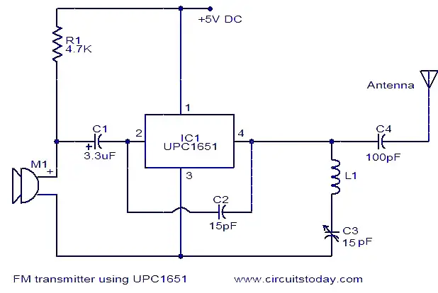
Pemancar FM dengan IC UPC1651

fm-transmitter-using-upc1651Here is the circuit diagram of an FM transmitter using the IC UPC1651. UPC1651 is a wide band UHF Silicon MMIC amplifier. The IC has a broad frequency response to 1200MHz and power gain up to 19dB.The IC can be operated from 5V DC.
The audio signals picked by the microphone are fed to the input pin (pin2) of the IC via capacitor C1. C1 acts as a noise filter. The modulated FM signal will be available at the output pin (pin4) of the IC. Inductor L1 and capacitor C3 forms the necessary LC circuit for creating the oscillations. Frequency of the transmitter can be varied by adjusting the capacitor C3.


Notes.
  • The circuit can be assembled on a Vero board.
  • Inductor L1 can be made by making 5 turns of 26SWG enameled copper wire on a 4mm diameter plastic former.
  • A ¾ meter insulated copper wire can be used as the antenna.
  • Do not give more than 6V to the IC.
  • Mic M1 can be a condenser microphone.

Jumat, 23 Maret 2012

Long range fm transmitter circuit diagram

Long range fm transmitter circuit diagram
This is very stable, harmonic free, long range fm transmitter circuit which can be used for fm frequencies between 88 and 108 MHz. This can cover 5km range (long distance). It has a very stable oscillator because you use LM7809 stabilizer which is a 9V stabilized power supply for T1 transistor and for frequency adjustment that can be achieved by using the 10K linear potentiometer.
The output power of this long range rf transmitter is around 1W but can be higher if you use transistors like KT920A, BLX65, BLY81, 2N3553, 2SC1970, 2SC1971…
T1 is used as an oscillator stage to deliver a low power stable frequency. To adjust the freq. use the 10k linear potentiometer like this: if you trim down, towards ground, the freq. will drop and if you adjust it toward + it will rise. Basically the potentiometer is used as a variable power supply for the two BB139 varicap diodes. Those two diodes act like a variable capacitor when you adjust the pot. By varying the diode capacitance the L1 + diodes circuit makes a resonance circuit for T1. You can use transistors like BF199, BF214 but do not use BCs. At this moment you don’t have yet the long range fm transmitter because the power is quite low, no more than 0.5 mW.
T2 and T3 works as a buffer stage, T2 as a voltage amplifier and T3 as a current amp. This buffer stage is very important for freq stabilization because is a tampon circuit between the oscillator and the preamp and final amplifier. It is well known that poor transmitter designs tend to modify freq. as you adjust the final stage. With this T2, T3 stage this won’t happen anymore!
T4 is a preamplifier for the fm transmitter and is used as a voltage power rf amplifier and will deliver enough power to the final T5 transistor. As you can see T4 has a capacitor trimmer in its collector, this is used to make a resonance circuit that will force T4 to amplify better and get rid of those unwanted harmonics. L2 and L3 coils must be at 90 degrees angle one to another, this is to avoid frequency and parasite coupling.
The final stage of the long range rf transmitter is equiped with any rf power transistor that has at least 1 watt output power. Use transistors like 2N3866, 2N4427, 2N3553, BLX65, KT920A, 2N3375, BLY81, 2SC1970 or 2SC1971 if you want to have a pro fm transmitter with enough power to cover a long range area. If you use 2N2219 you will get no more than 400mW. Use a good heatsink for the T5 transistor as it gets a little hot. Use a good 12V/1Amp minimum stabilized power supply.

T1 = T2 = T3 = T4 = BF199
T5 = 2N3866, 2N4427 or 2SC1970 for 1Watt / 2SC1971, BLX65, BLY81, KT920A or 2N3553 for 1.5 to 2W power.
L1 = 5 turns / 0.6mm / 4mm silvered copper
L2 = 6 turns / 0.8mm / 6mm enamelled copper
L3 = 3 turns / 1mm / 7mm silvered copper
L4 = 6 turns / 1mm / 6mm enamelled copper
L5 = 4 turns / 1mm / 7mm silvered copper
Use silvered copper for L3 and L5 if you want to obtain better characteristics.

Adjustments of the long range transmitter

Start by construction the oscillator stage, solder a small wire to T1 10pF capacitor out and listening to a fm receiver, trim the 10k pot untill you can “hear” a blank noise or you you plug in an audio source you can hear the music. With a 70cm wire you can cover a 2 – 3 meter area just with the oscillator stage.
Then continue to build the rest of the rf transmitter, use proper shielding as indicated in the circuit schematic. When you finished the transmitter construction connect the antena or better a 50 or 75 Ω resistive load and use this rf probe, you can use 1N4148 diode instead of the probe diode.
Adjust again the 10k pot to desired freq. and then go to T4 stage and trim the first collector trimmer for maximum voltage indication on the multimeter. Then continue with the next trimmer and so on. Then go back to the first trimmer and readjust again untill you obtain the highest voltage on the multimeter. For 1 watt rf power you can measure a 12 to 16 Voltage. The formula is P (in watt) is equal to U2 / Z, where Z is 150 for 75Ω resistor or 100 for 50Ω resistor, but you must remember that the real rf power is lower.
After those adjustment, if everything is going well connect the antenna, continue using the rf probe, readjust again all the trimmers starting from T3. Make sure you don’t have harmonics, check your TV and radio set to see if there is disturbance on the band. Check this in another room, far away from the fm transmitter or antenna.
That’s all folks :D … This is my design for a long range transmiter and is working well. I used 2SC1971 which has a 12dB power gain in 88 … 108 MHz band, this is around 15 times rf amplification. As T4 delivers around 80 to 100 mW of rf power the final stage has enough power to deliver between 1 to 2W depending the transistor usage.

1 Watt Four Stage FM Transmitter

This FM transmitter circuit uses four radio frequency stages: a VHF oscillator built around transistor BF494 (T1), a preamplifier built around transistor BF200 (T2), a driver built around transistor 2N2219 (T3) and a power amplifier built around transistor 2N3866 (T4).

FM Transmitter circuit diagram

A condenser microphone is connected at the input of the oscillator. Working of the 1 Watt transmitter circuit is simple. When you speak near the microphone, frequency-modulated signals are obtained at the collector of oscillator transistor T1.

The FM signals are amplified by the VHF preamplifier and the pre-driver stage. You can also use transistor 2N5109 in place of 2N2219. The preamplifier is a tuned class-A RF amplifier and the driver is a class-C amplifier. Signals are finally fed to the class-C RF power amplifier, which delivers RF power to a 50-ohm horizontal dipole or ground plane antenna.
Use a heat-sink with transistor 2N3866 for heat dissipation (Note: or 2N4427 because it works better at 12 V and delivers up to 1 watt RF power). Carefully adjust trimmer VC1 connected across L1 to generate frequency within 88-108 MHz. Also adjust trimmers VC2 through VC7 to get maximum output at maximum range.
Regulator IC 78C09 provides stable 9V supply to the oscillator, so variation in the supply voltage will not affect the frequency generated. You can also use a 12V battery to power the circuit. Assemble the circuit on a general purpose PCB. Install the antenna properly for maximum range.
Coils L1 through L5 are made with 20 SWG copper-enamelled wire wound over air-cores having 8mm diameter. They have 4, 6, 6, 5 and 7 turns of wire, respectively.

3 Volt FM Transmitter

Rangkaian 3V FM Transmitter
Skema Rangkaian 3V FM Transmitter
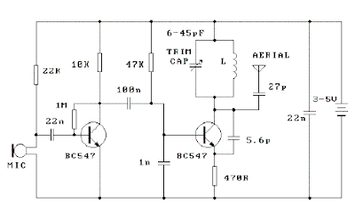
This 3V FM transmitter is about the simplest and most basic transmitter to build and have a useful transmitting range. It is surprisingly powerful despite its small component count and 3V operating voltage. It will easily penetrate over three floors of an apartment building and go over 300 meters in the open air.

The circuit is basically a radio frequency (RF) oscillator that operates around 100 MHz. Audio picked up andamplified by the
electret microphone is fed into the audio amplifier stage built around the first transistor. Output from the collector is fed into the base of the second transistor where it modulates the resonant frequency of the tank circuit (the 5 turn coil and the trimcap) by varying the junction capacitance of the transistor. Junction capacitance is a function of the potential difference applied to the base of the transistor. The tank circuit is connected in a Colpitts

Place the transmitter about 10 feet from a FM radio. Set the radio to somewhere about 89 - 90 MHz. Walk back tothe FM transmitter and turn it on. Spread the winding of the coil apart by approximately 1mm from each other. No coilwinding should be touching another winding. Use a small screw driver to tune the trim cap. Remove the screwdriverfrom the trim screw after every adjustment so the LC circuit is not affected by stray capicitance. Or use a plasticscrewdriver. If you have difficulty finding the transmitting frequency then have a second person tune up and downthe FM dial after every adjustment. One full turn of the trim cap will cover its full range of capacitance from 6pF to 45pF. The normal FM band tunes in over about one tenth of the full range of the tuning cap.

So it is best to adjust it in steps of 5 to 10 degrees at each turn. So tuning takes a little patience but is not difficult. The reason that there must be at least 10 ft. separation between the radio and the FM transmitter is that the FM transmitter emits harmonics; it does not only emit on one frequency but on several different frequencies close to each other. You should have little difficulty in finding the Tx frequency when you follow this procedure.

Kamis, 15 Maret 2012

FM Transmitter 12 Watt


The advantages of FM modulation is free from the influence of air disturbance, the bandwidth (wide band) is larger, and the high fidelitas. If compared with the AM system.

fm transmitter is a modification of the fm transmitter on the market (type of saturn s 038). with several series of modifications and additions boster series can produce power at around 12 watts


try in the series after this work is quite good, the signal generated is stable and strong enough
up time should not in a hurry to do directly, but overall do each part in sequence so that the error may be earlier

the first part of the work is in the oscillator, after the raft can try in turn to the way radio waves on the free and set the radio volume so clearly audible hissing sound. turn up the core koker hissing sound on the radio is missing, if you get a signal in a robust and stable means that the set of oscillator has been working with both.

the next section can start at the raft, after finished the second set trimer (C8 and C11) in the buffer in turn can power up in most large and most small SWR. If the series works well, will produce approximately 0.25 watt power

to get more resources than most can add more series boster 12 watt range, so the distance will be increased to reach 7-fold


12 watt Boster Circuit FM transmitter